Welcome to XiYu

Sheet Metal Bending: Methods and Design Considerations
Explore sheet metal bending methods, bend allowance, tooling, radius, and design factors that help improve accuracy and reduce fabrication problems.

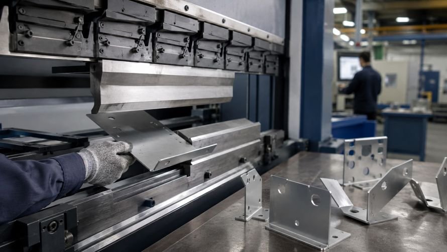
Sheet metal bending is the process of forming a flat metal blank into an angle, channel, bracket, enclosure panel, or other three-dimensional shape. It is a core step in custom fabrication because a part may begin as a laser-cut flat pattern but only becomes functional after its flanges, walls, mounting faces, or protective covers are formed.
For OEM buyers, a successful bending project depends on more than choosing a bend angle. Material type, thickness, bend radius, hole locations, tolerances, surface requirements, and the part’s assembly function all influence whether the finished component can be made consistently and economically.
What Is Sheet Metal Bending?
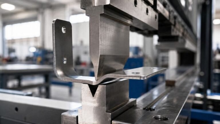
Sheet metal bending uses controlled force to form a flat sheet around tooling. A press brake is commonly used for brackets, panels, trays, enclosures, covers, and structural components. The machine applies force along a programmed bend line, while the selected upper and lower tooling guides the material into the required form.
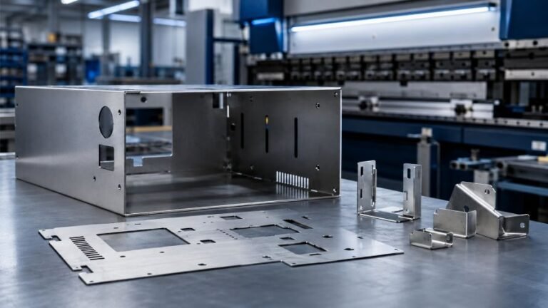
Bending is normally part of a wider sheet metal fabrication workflow. The flat blank may first be cut, then formed, deburred, fitted with hardware, welded, finished, assembled, and inspected.
A drawing that looks simple in flat form can become more demanding after bending. Flanges may need clearance from nearby holes, formed edges may affect assembly access, and the material may need a practical bend radius to reduce cracking or distortion.
Common Sheet Metal Bending Methods
Different methods suit different materials, thicknesses, geometries, and production needs.
| Method | How It Works | Often Suitable For | Buyer Consideration |
|---|---|---|---|
| Air bending | The material is pressed into a lower V opening without fully contacting every surface. | Flexible angles, varied part designs, and many custom OEM parts. | Allows a range of angles, but springback must be considered. |
| Bottom bending | The material is formed more closely against the lower tooling. | Parts that need more consistent formed angles. | Tooling selection and material properties still affect the result. |
| Coining | Higher force is used to form the bend very precisely. | Specific applications with strict forming requirements. | May require greater force and a more specialized process review. |
| Panel folding | A folding machine forms a flange by moving the sheet edge. | Larger panels, covers, and parts where surface handling matters. | Useful when the geometry and edge treatment suit the process. |
| Roll bending | Sheet metal passes through rollers to create curved forms. | Cylindrical covers, curved panels, and larger-radius components. | Usually selected for curves rather than sharp-angle bends. |
The best method should be selected from the finished-part requirement, not from the bend operation alone. A supplier needs to understand how the part will be assembled, loaded, finished, and inspected.
From Flat Pattern to Formed Part
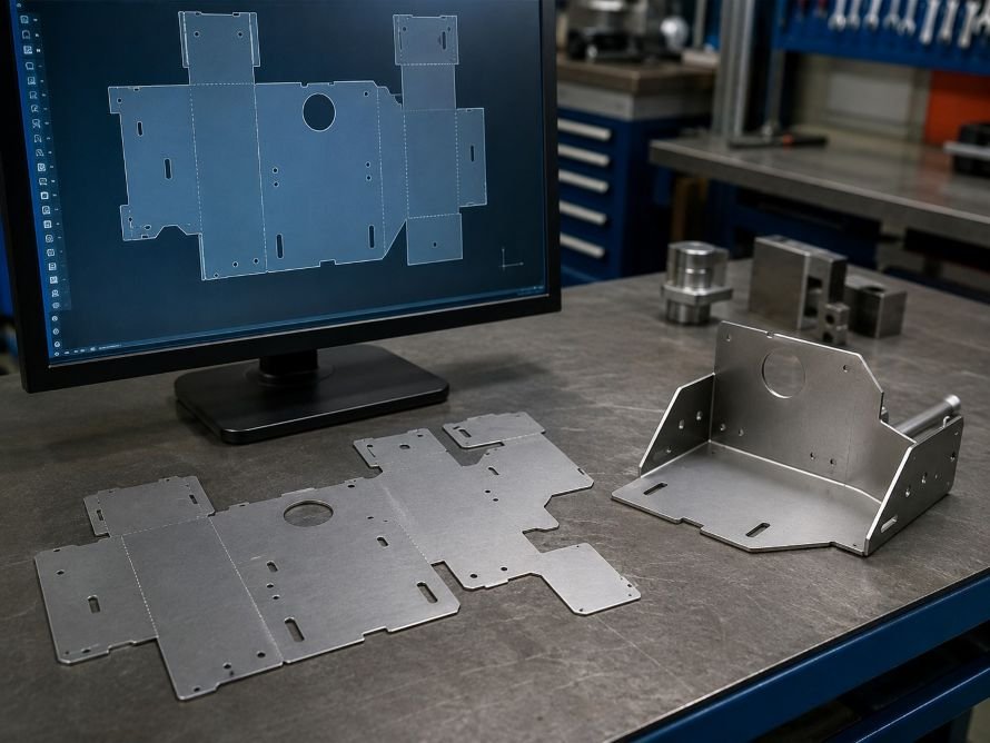
A typical process begins with a drawing or CAD review. The flat pattern is checked together with the required bends, material, thickness, holes, slots, tolerance requirements, and any secondary operations.
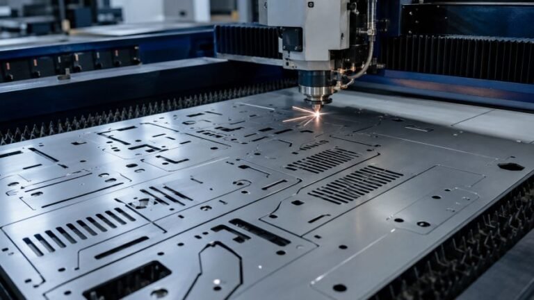
If the part requires complex cutouts before forming, sheet metal laser cutting can create the flat profile before the component moves to bending. This sequence is common for custom brackets, enclosure panels, machine guards, and mounting structures.
The manufacturer then plans bend order, tooling, handling, and inspection points. Bend order matters because an early flange can limit access for a later bend. A practical process route prevents collisions, reduces unnecessary handling, and helps retain the dimensions that matter to fit and function.
Design Factors That Affect Sheet Metal Bending
Good bending design connects the flat pattern with the final formed shape. The following factors should be reviewed before production.
| Design Factor | Why It Matters | Practical Buyer Guidance |
|---|---|---|
| Material type | Different materials respond differently to forming. | State the material grade or approved equivalent in the RFQ. |
| Sheet thickness | Thickness affects bending force, radius, springback, and part stiffness. | Confirm thickness with both functional and assembly requirements. |
| Inside bend radius | A radius that is too tight may increase the risk of cracking or visible marking. | Specify critical radii and review material suitability early. |
| Bend allowance | Material stretches and compresses during forming. | Use a controlled flat-pattern calculation instead of assuming formed dimensions transfer directly. |
| Grain direction | Material orientation can influence how it forms. | Highlight sensitive bends or cosmetic surfaces when relevant. |
| Hole and slot location | Features placed too close to a bend can distort or interfere with forming. | Identify fit-critical holes, threads, and mounting features. |
| Flange length | Very short flanges may need special tooling or may not be practical. | Confirm the finished flange requirement, not only the flat drawing. |
| Tolerances | A formed dimension may be affected by material, tooling, and measurement method. | Separate critical assembly dimensions from general dimensions. |
Bend allowance, bend deduction, and K-factor are drawing-calculation tools used to convert finished formed geometry into a workable flat pattern. Buyers do not need to calculate every value themselves, but they should ensure that the supplier receives the intended formed dimensions, material information, and critical requirements.
What Affects Bend Quality?
The final quality of a bent part depends on the complete process. A clean laser-cut blank alone does not guarantee that the formed part will meet every requirement.
| Quality Area | What Can Affect It | What to Specify |
|---|---|---|
| Bend angle | Springback, tooling, material condition, and thickness. | Critical angles and permitted variation. |
| Bend radius | Material properties, thickness, and selected tooling. | Functional or cosmetic radius requirements. |
| Flatness | Part geometry, bend sequence, residual stress, and handling. | Surfaces that must sit flat during assembly. |
| Hole position after forming | Flat-pattern design, bend location, and material movement. | Assembly-critical holes, slots, and interfaces. |
| Surface appearance | Tool contact, protective film, material finish, and handling. | Cosmetic surfaces, coating requirements, and scratch limits. |
| Edge condition | Cutting method, deburring, and post-forming handling. | Requirements for safe handling, coating, or visible edges. |

Inspection should be planned around the dimensions that affect the part’s real function. For example, a mounting bracket may need accurate hole-to-bend position, while a cover may prioritize visual alignment, consistent gaps, and a clean finished surface.
When Is Sheet Metal Bending a Good Fit?
Sheet metal bending is widely used when a part needs strength and shape without being machined from solid stock. It is often a good fit for:
- Mounting brackets and support structures
- Electrical and electronics enclosures
- Control panels and chassis parts
- Machine covers and guards
- Lighting housings and frames
- Cabinets, trays, and access panels
- Automotive and industrial equipment components
- Custom assemblies that combine cutting, forming, hardware, and finishing

For stable, high-volume designs, precision metal stamping may be worth evaluating as a separate manufacturing route. The right choice depends on volume, geometry, tooling investment, revision frequency, and the complete cost of the finished component.
What Should Buyers Include in a Sheet Metal Bending RFQ?
A complete RFQ helps a manufacturer review the part accurately and identify potential issues before production.
| RFQ Item | Why It Helps | Example |
|---|---|---|
| Formed-part drawing or CAD file | Defines the required final geometry. | 2D drawing, 3D model, or approved revision file. |
| Material and thickness | Supports tooling and process planning. | Material type, thickness, and any required grade. |
| Quantity | Helps determine a practical manufacturing route. | Prototype quantity, trial order, and estimated annual volume. |
| Critical dimensions | Directs inspection to fit and function. | Hole-to-bend location, angle, flatness, or assembly interfaces. |
| Surface requirement | Clarifies cosmetic and corrosion needs. | Deburring, coating, plating, brushing, or protective film. |
| Secondary operations | Shows what happens after bending. | Hardware insertion, welding, assembly, labeling, and packaging. |
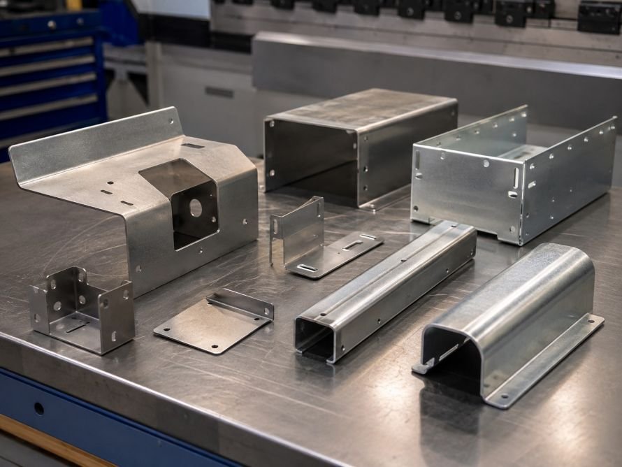
If the part mates with another component, include enough assembly context for the supplier to understand clearance, access, fastener locations, and inspection priorities.
FAQ
What is the difference between laser cutting and sheet metal bending?
Laser cutting creates the flat outline, holes, slots, and cutouts. Sheet metal bending forms that flat blank into a three-dimensional part. Many OEM components need both processes.
Can a hole be placed close to a bend?
It can, but the location should be reviewed carefully. A feature too close to a bend may distort during forming or create tooling interference. Mark assembly-critical features clearly in the drawing.
Why do bent parts sometimes spring back?
Some materials recover slightly after forming. Material type, thickness, bend radius, and tooling all affect springback. The manufacturing process can be adjusted to account for it.
Request a Quote for Custom Bent Sheet Metal Parts
If you are sourcing custom bent brackets, panels, enclosures, covers, or formed assemblies, send your drawing, material preference, quantity, and application requirements. Contact us to discuss a practical fabrication route for your OEM or ODM project.