Welcome to XiYu

Sheet Metal Bend Radius: What Is the Minimum?
Understand sheet metal bend radius, what determines the minimum practical radius, and how material, thickness, and tooling affect bend design.

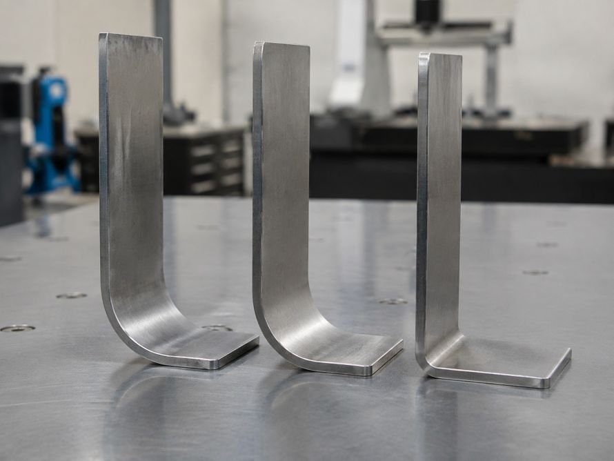
A sheet metal bend radius is the inside curve created when a flat metal blank is formed. There is no single minimum sheet metal bend radius that works for every part. The practical minimum depends on the material, thickness, temper, grain direction, tooling, bend angle, and the features located near the bend.
For OEM buyers and design engineers, the right question is not simply “What is the smallest radius?” It is “What radius can be formed consistently while protecting part function, appearance, and production repeatability?”
What Does Sheet Metal Bend Radius Mean?
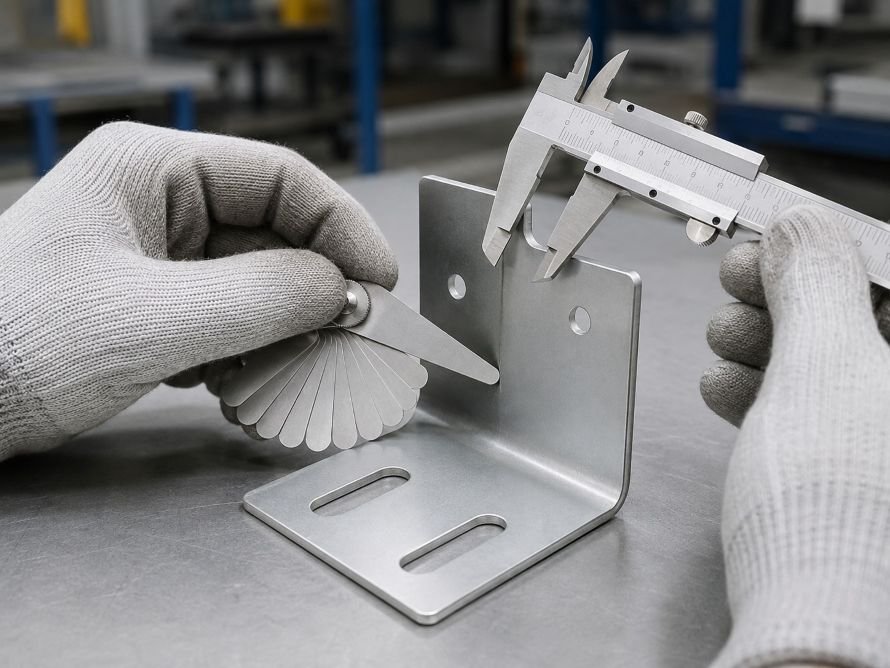
In most drawings, bend radius refers to the inside radius of the formed corner. The outside radius is larger because it includes the material thickness. This distinction matters when calculating the flat pattern, checking fit with mating parts, or setting clearance around an enclosure, bracket, or mounting feature.
Bend radius is a core part of the sheet metal bending process. A radius that is too small can place excessive strain on the outside surface of the bend. A radius that is too large may change the part envelope, reduce stiffness in some designs, or create an unintended fit issue.
What Determines the Minimum Practical Bend Radius?
Several design and process variables work together. A minimum radius should be reviewed as part of the complete part design, not selected in isolation.
| Factor | Why It Matters | Design Check |
|---|---|---|
| Material type and condition | Different materials and tempers have different forming behavior. | Confirm the exact material condition before releasing the drawing. |
| Material thickness | Thicker material usually needs more attention to radius and tooling selection. | Keep the stated thickness consistent across the drawing and BOM. |
| Grain direction | Bending across or along the rolling direction can affect cracking risk. | Show grain-direction requirements when they matter. |
| Tooling geometry | Punch shape and lower tooling opening influence the formed radius. | Ask the manufacturer to review the proposed bend setup. |
| Features near the bend | Holes, slots, embosses, and cutouts can distort during forming. | Leave adequate clearance or use relief features where needed. |
| Surface and finish needs | Cosmetic surfaces may need extra protection during forming. | Identify visible faces and finish-critical areas. |

What Problems Can a Radius That Is Too Small Cause?
The most visible issue is cracking or surface stretching on the outside of the bend. However, a tight radius can also create less obvious production problems:
- Variation in the formed angle or springback from part to part.
- Distortion around nearby holes, slots, and edge features.
- Marking or damage on finish-sensitive surfaces.
- Higher setup risk when the required geometry is difficult to form repeatedly.
This does not mean every part needs a large radius. It means the selected radius should be suitable for the material and the finished-part requirement.
How Should You Set a Minimum Bend Radius?
Start with the actual part requirements rather than a universal rule of thumb.
First, specify the material, thickness, and any condition that could affect formability. Generic material descriptions leave too much room for interpretation when a bend is close to a forming limit.
Second, decide whether the inside radius is functionally important. For example, a tight radius may be required to fit into a compact assembly, while a larger radius may be acceptable on a non-critical bracket.
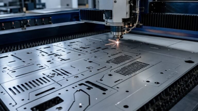
Third, review the bend in relation to nearby features. Holes, tabs, slots, and cutouts positioned too close to a bend can stretch, deform, or move during forming. When the flat pattern contains complex profiles, the earlier sheet metal laser cutting stage should also be considered as part of the overall fabrication plan.
Finally, confirm the design with production-intent material and tooling before relying on a small radius for a larger order. A sample review can reveal issues that are not obvious from a CAD model alone.
How Does Bend Radius Affect the Flat Pattern?
Bend radius affects the length of material consumed in the bend area. This is why bend allowance, bend deduction, and the neutral axis need to be handled consistently when creating the flat pattern.
A correct flat pattern helps the finished part meet its intended dimensions after forming. It also reduces unnecessary trial adjustments between cutting and bending. For broader context on the sequence from flat blank to finished component, see our guide to sheet metal fabrication.
What Should Be Included on the Drawing?
A clear drawing helps the manufacturer review bend feasibility early. Include the following where relevant:
| Drawing Detail | Why It Helps |
|---|---|
| Material and thickness | Establishes the starting point for forming review. |
| Inside bend radius | Prevents assumptions about the required formed geometry. |
| Bend angle and direction | Clarifies how each flange or return is formed. |
| Critical dimensions after bending | Identifies the dimensions that control assembly fit. |
| Feature-to-bend clearance | Highlights holes, slots, and cutouts that need review. |
| Cosmetic or finish-critical surfaces | Helps plan handling and forming protection. |
When Should You Ask for a Manufacturing Review?
A review is especially useful when a design includes a very tight radius, thicker material, several closely spaced bends, cosmetic surfaces, or features positioned near a bend. It is also valuable when the part must fit with stamped, machined, or purchased components.
Sharing a complete drawing, material requirement, expected application, and critical dimensions gives the manufacturing team a better basis for evaluating the bend design before production begins.
FAQ
Is the inside radius the same as the outside radius?
No. The inside radius is measured on the inner surface of the bend. The outside radius is larger because it includes the material thickness.
Can one minimum radius be used for all sheet metal materials?
No. Material type, thickness, temper, and grain direction can all change how a material behaves during forming. Use the actual material specification when reviewing a bend requirement.
Does laser cutting determine the bend radius?
Laser cutting does not create the bend radius itself, but cut features near the bend can affect how the part forms. Hole position, slot shape, and edge clearance should be reviewed together with the bending requirement.
Need a Review of Your Sheet Metal Bend Design?
For a custom OEM sheet metal project, share your drawing, material requirement, and critical formed dimensions with our team. Contact us to discuss the next step.